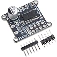
UMLIFE 3pcs AS5600 Magnetic Encoder Sensor Module 12bit High Precision for Computer, Camera, Smartphone
| Brand | UMLIFE |
| Series | AS5600 Magnetic Encoder |
| Operating System | Linux |
| Item Weight | 0.176 ounces |
| Product Dimensions | 0.91 x 0.91 x 0.91 inches |
| Item Dimensions LxWxH | 0.91 x 0.91 x 0.91 inches |
| Color | 3PCS |
| Processor Brand | ARM |
| Number of Processors | 1 |
| Manufacturer | UMLIFE |
| ASIN | B094F8H591 |
| Country of Origin | China |
| Date First Available | May 8, 2021 |
D**S
Works Well I2C at 5V
I used a basic proven sketch to test hardware functionality. The one I used can be found searching "cybertice" in google.Overview of the setup required.- For people just tinkering. The tiny board but that has it's benefits for your builds. If you have high heat on your soldering iron try to control it the best you can on the low end for your solders temp specification. Use LED based solder for better control from my experience with these.- I2C setup right out of the bag, don't change anything if you want the best resolution at 5v. If you need analog take the R4 resistor out. about that in the manual.- To test hardware functionality before attempting to code; try searching "cybertice". There was a great instructional/source code there on their page and githubs without the use of an LCD screen.- Pinout as follows: * Pin (2) for DIR (default in the cybertice library) * Pin SDA and SCL to the Arduino * 5v and GND- After you download their library run the example "readAngle" and approach the magnet within the 0.5mm-3mm spec works greatI will purchase more of these now. 5pcs it is. (Lots of 3d prints available for these already, just search for them) Read more
C**S
Works as expected, with one modification
I had to remove the R1 and R4 resistors and use 5vdc input to get the described analog output on out pin. I2C still works fine with the resistors removed. It may be that only one of R1 or R4 needs to be removed, but I didn't try that. With that change I was able to see a very consistent 0-5 vdc change that corresponded to 0-360 degree rotation. 90 degrees was 1.25 vdc, and 180 degrees was 2.5vdc, and 270 degrees was 3.75 vdc. right at 0/360 degrees, the voltage changed from 0 to 5 vdc. Now very happy.
S**S
Good product---Mind the configuration!
These work great, but they are wired for I2C ONLY! If you are looking for analog output, you will need to REMOVE the resistor which is connected to the PG0 pin (pin #8). then you will get an analog voltage output, at the out pin on the board. Without this, the output voltage will always be at Vcc (3.3 or 5V). Hope this helps someone....otherwise, they work great!
D**Y
Versatile, Excellent Resolution
The media could not be loaded. I will not say that this device is easy to use but it works really well. If you have used a similar device before you may find it easy, but if you have not used and encoder like this it can be challenging, but it is definitely worth the time spent.There are three encoders in this package and all three come with a magnet. The magnet is important because this is a special type of magnet to make the encoder work. Typical magnets have north and south poles on either of the flat sides. This magnet is a diametrically magnetized. Imagine a line down the center of the flat side. The left side of the line is the North Pole, and the right side is the South Pole.The magnet is placed flat side over the chip (recommend .5 to 3mm gap). When the magnet is rotated around its center perpendicular to the surface, the chip can measure the amount of rotation (watch the video to see this in action).For this device to work, the magnet (or a similar one) must be attached to a rotating device such as a motor shaft or a manually controlled knob. The chip must be mounted within .5 to 3mm of the surface of the magnet directly centered for best results.The chip uses I2C for communications and probably is the best way to interact whit the device. Through this interface the device can be configured and the position of the angle as well as the strength of the magnet can be retrieved. The device can also output a proportional voltage or PWM signal on the output pin as the angle is changed. This output mode is set using the I2Cz interface. See the data sheet for more information.The DIR pin selects the polarity of the output with regard to rotation direction. If this pin is connected to GND, the output value increases with clockwise rotation. If DIR is connected to VDD, the output value increases with counterclockwise rotation.The device uses a 12-bit ADC which means a full angle of 360˚ is divided by 4096 measurements giving a resolution of 0.08789˚. This resolution allows the encoder to be used for many stepper motor applications.Take a typical 3D printer stepper motor. This stepper will have 1.8˚ of resolution (200 steps per turn). This is well within the resolution of the encoder. Most 3D printers, however, use microstepping. Let’s say we enabled 16 microsteps for example. This would result in 3200 steps per turn (.1125˚ of motor resolution) which is still within the resolution of this device. If we set our microstepping to 32 (0.05625˚ of motor resolution), the device would not be able to measure every change of a stepper motor.To get up and running I used an Arduino Uno and the Seeed-Studio library. The library is not available through the Arduino library manager. Just search the Internet for it and add it manually. If you have access to a 3D printer, you can print a holder and knob for the magnet for testing purposes. Search AS5600 on Thingiverse. There are also some great videos on YouTube that will help get you started as well as demonstrate various ways this encoder can be used.Watch the video to see the encoder in action.
G**N
A nice absolute angle sensor
These are really interesting sensors. They return the absolute angle of the special magnet placed over them. So on startup you will get the actual position of the magnet, so if it's at the 0 degree position, 0 is what you will get. Other types of encoders are relative, that is they tell you how many degrees left or right they have been turned, but don't give you the actual position.This type of encoder is nice for things where you want to know the actual angle right from the time it starts up, for example the steering angle on on a car or the volume setting on a volume knob. They only read out 0-360 degrees so if you want to measure multiple turns you have to do that in software (not hard).To use this you need the right kind of magnet, the line between the north/south poles of the magnet has to be perpendicular to the top of the chip. Most disc magnets are magnetized with north and south through the thin part of the disc ie: if it was a coin, heads would be north and tales would south these magnets won't work. Again if this was a coin, you would need it to be magnetized with north on the left and south on the right. The magnets included with these are magnetized this way. If you happen to lose them, you can buy this type of magnet on the internet.These are good for a lot of things like measuring the position of a servomotor, digital control dials, measuring position of a weathervane and similar things.It appears that these only communicate by the I2C two pin protocol. This is fairly easy to use but may have some limitations on how fast you can read the data. Since these are absolute angle sensors you don't have to read them fast, they will give you the actual angle of the magnet whenever you read them.
Trustpilot
1 month ago
1 month ago