
Desert Online General Trading LLC
Dubai, United Arab Emirates
Desert Online General Trading LLC
Dubai, United Arab Emirates


📊 Display Your Genius with Every Project!
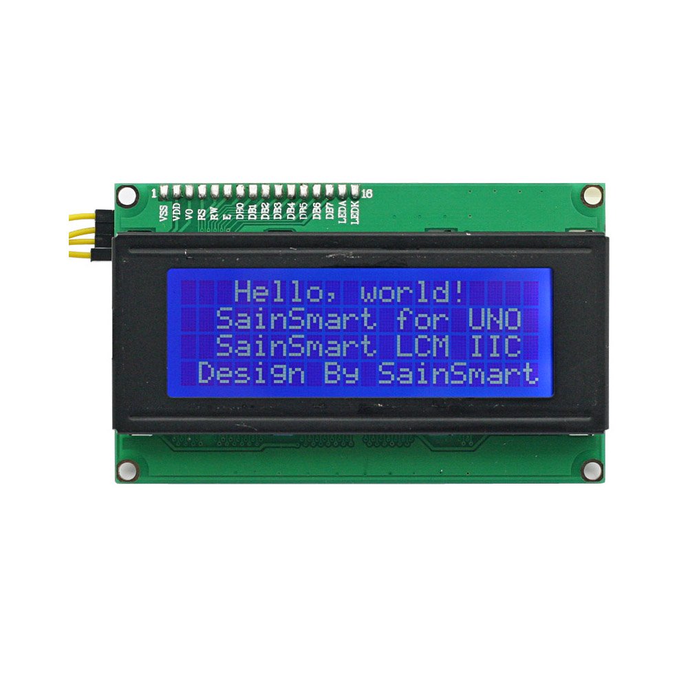
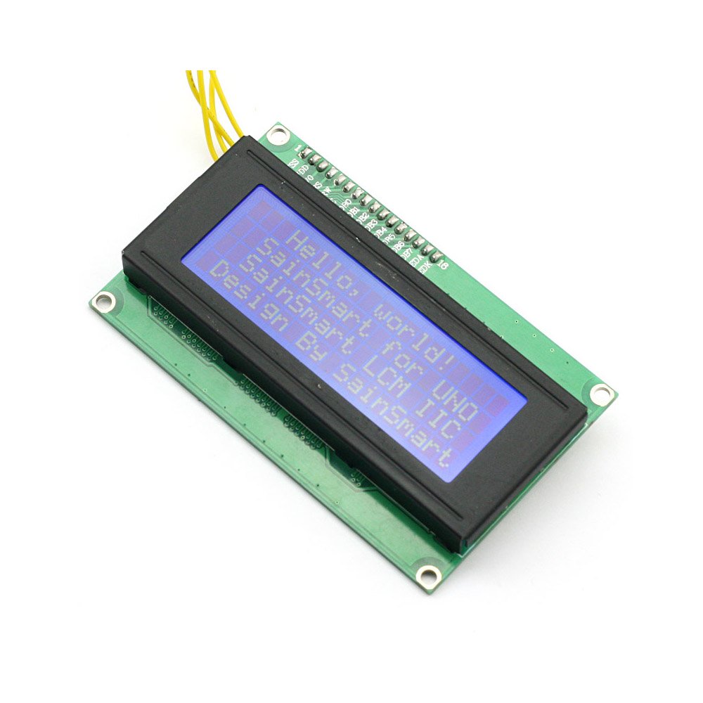
The SainSmart IIC/I2C/TWI Serial 2004 20x4 LCD Module Shield is a cutting-edge display solution for Arduino enthusiasts, featuring a 20x4 character layout and an I2C interface for simplified connections. Perfect for a variety of applications, this module is designed to enhance your projects with clarity and style.
L**F
Digistump DigiX with LCD2004 and I2C level shifter
I'm using this with a Digistump DigiX, and it works very nicely. I like the white display on blue backlight.Some notes which I hope may be useful to others:- If it doesn't seem to work at first, some suggestions: a- check the I2C address, that's probably the main culprit (see below) b- if your Arduino has more than 1 I2C bus, check you are using the right one. c- check the voltage level on the IIC, the 2 pins on the left above the LCD are ground followed by Vcc, should be 5V.- There seems to be a lot of confusion on the I2C address. Mine was on the expected 0x27 address.There are 2 versions of the i2c chip which differ in their address and I suspect that's why some people indicate they need to use address 0x3F instead of 0x27. Explanation follows.Look on the back at the marking on the i2c chip, it's going to be either a PCF8574T or a PCF8574AT.The address is fixed by the 3 pins #1, #2 and #3 of the PCF8574, which you can verify are all connected to Vcc.Next check page 9 of the datasheet from http://www.nxp.com/documents/data_sheet/PCF8574.pdf :- For the "T" version, the address is going to be [0 1 0 0 A2 A1 A0], which is 0x27.- For the "AT" version, the address is going to be [0 1 1 1 A2 A1 A0], which is 0x3F.- The DigiX, like the Arduino DUE or a Raspberry Pi, uses 3.3V I/O. You MUST NOT connect this directly on the I2C bus when powering the LCD via 5V. Instead just grab any i2c level shifter, for example something like Logic Level Converter or any similar board.- The I2C chip PCF8574T should work fine with a 3.3V level, and the HD44780 is supposed too. However when I tried, this was not enough to power the whole display. I had to provide 5V to Vcc and use a level shifter for the I2C SDA and SCL.- The DigiX from Digistump did not require any extra LiquidCrystal_I2C library: it's already included in the DigiX libraries. However the DigiX has 2 I2C buses, and the library by default uses Wire1, which is pins 70 and 71. To try it out, use Examples > DigiX > DigiXLCD > BasicUsage in the Arduino IDE if configured with the DigiX libraries.- The library has an LCD::backlight() and noBacklight() functions which work well. The display is NOT readable with the backlight turned off.- Note that by default the display line "wraps" around (from line 1 to 3 then to 2 then to 4). Internally the HD44780 has 80 bytes of display. The default LCD::print() method thus wraps at the end of the line to the next logical line unless you clip/trim your strings.- On the back of the I2C board there's a red led when powered and a jumper to deactivate it. There's also a little knob to adjust the contrast -- it only changes the white dots contrasts and does not adjust the level of the blue backlight.
K**R
Works great with a little research
The first few attempts trying to get the board working with Rev. 1.0.1 of the Arduino IDE did not go well. Only after searching the web and stumbling upon F Malpartida's enhanced liquid crystal library did things coalesce. The device is fixed at I2C address 0x27, which sucks, since you can't string multiple LCDs on different I2C addresses for more information. The display itself should be five stars, but the annoyance factor in finding code that worked and the non-addressability reduce it to 2-1/2 stars which on this site rounds up to three.
P**.
Works good thanks to Internet as there are no docs with it (not even the correct I2C address)
It worked out of the box: this is what worked for me:1. add the Arduino LCD library (search for the one called LiquidCrystal I2C aka. YWROBOT)2. connect the 4 pins (SDA=A4/SCL=A5/GND/VCC=5V) Note: this is for Arduino Uno, SCL/SDA are in other pins on different devices3. I kept the jumper on the pins labeled "LED"4. Open HelloWorld from LCD lib example5. just changed the address (0x27 instead of 0x3F but YMMV)):LiquidCrystal_I2C lcd(0x27,20,4); // set the LCD address to 0x27Compile,upload, works!Note i found 0x27 as one of the 2 possible ones in the datasheets of the I2C chip (PCF8574 vs PCF8574A).The one in my LCD reads as PCF8574T.Much of the confusion with this LCD display comes from several versions with those 2 chip addresses (dependent on the used I2C chip PCF8574 vs PCF8574A - though mine reads PCF8574T not PCF8574AT).I noticed there is another (older?) library that requires more pin setup than the one i used,not sure if i lose functionality with it but it works great for what i need and simpler=better to me.
C**I
No Box, No code, No schemtic, No cables but nice display.... Here is code for you to use!
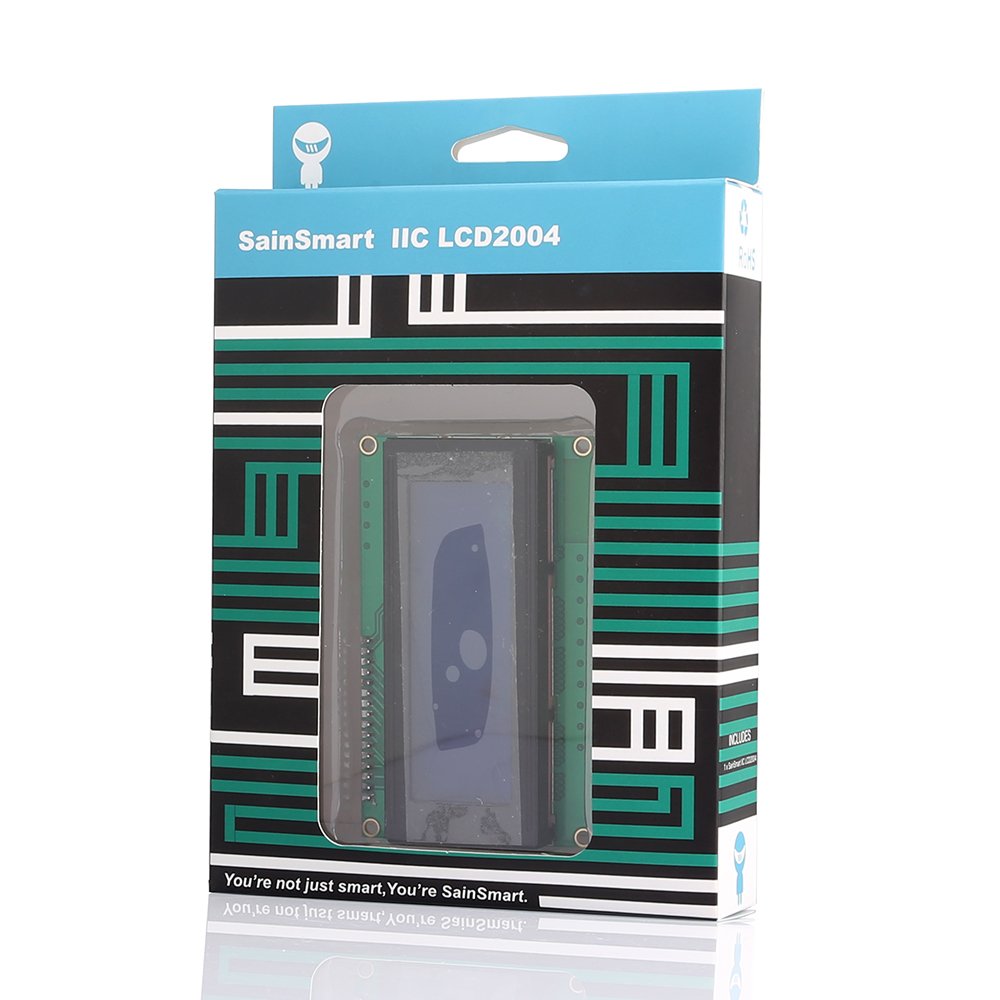
Screen came without the pretty box in the picture, no codes, no cables. The address of the unit is different from other postings I have seen. Mine was (0x27) A previous post listed some code you can use, but the code did not include the lcd.clear(function) and the ordering was wrong. Here is adjusted code for you to use./*** Example Arduino sketch for SainSmart I2C LCD2004 adapter for HD44780 LCD screens** Readily found on eBay or [...]** The LCD2004 module appears to be identical to one marketed by YwRobot**** Edward Comer** LICENSE: GNU General Public License, version 3 (GPL-3.0)**** sain_lcd_2.ino** Simplified and modified by Andrew Scott for Arudino 1.0.1, Arudino Uno R3.** NOTE: I2C pins are A4 SDA, A5 SCL** Don't forget to use the new LiquidCrystal Library from [...]*/#include <Wire.h>#include <LCD.h>#include <LiquidCrystal_I2C.h>#define I2C_ADDR 0x27 // Define I2C Address where the SainSmart LCD is#define BACKLIGHT_PIN 3//LiquidCrystal_I2C lcd(I2C_ADDR,En_pin,Rw_pin,Rs_pin,D4_pin,D5_pin,D6_pin,D7_pin);LiquidCrystal_I2C lcd(I2C_ADDR,2,1,0,4,5,6,7);void setup(){ lcd.begin (20, 4); // Switch on the backlight lcd.setBacklightPin(3,POSITIVE); lcd.setBacklight(HIGH); lcd.home();}void loop() { lcd.clear(); lcd.setCursor ( 0, 0 ); lcd.print("LUKE!"); lcd.setCursor ( 0, 1 ); lcd.print("I AM your...."); lcd.setCursor ( 0, 2 ); lcd.print("Father!!!"); lcd.setCursor ( 0, 3 ); lcd.print("Join ME and we"); delay(3000); lcd.clear(); lcd.setCursor ( 0, 0 ); lcd.print("Will RULE the"); lcd.setCursor ( 0, 1 ); lcd.print("GALAXY!!!!"); lcd.setCursor ( 0, 2 ); lcd.print("Do not hide"); lcd.setCursor ( 0, 3 ); lcd.print("from your"); delay(3000); lcd.clear(); lcd.setCursor ( 0, 0 ); lcd.print("TRUE Feelings"); lcd.setCursor ( 0, 1 ); lcd.print("Look inside,"); lcd.setCursor ( 0, 2 ); lcd.print("FEEL the POWER"); lcd.setCursor ( 0, 3 ); lcd.print("of the DARK SIDE!!!"); delay(3000);}
C**S
Your display may be different
Pros:Low PriceWorks wellCons:I2C address was not 0x3F as listed in the description. Not a big deal. A surprise, since other reviews had that address.Using the LiquidCrystal_I2C library to communicate with this display has changed since past reviews, and definitely from the description.To get this display to work, I went to arduino-info's LCD-Blue-I2C page, downloaded the library as linked on the site and used the example sketch labelled:"Example Software Sketch for 4 line 20 character Displays:(NOTE: for displays with backpack interface labelled "YwRobot Arduino LCM1602 IIC V1")"It appears that changes have been made with the library to accommodate more I2C display adapters, so this display needs a little more configuration. Not a big deal, especially since others have done it before me. If previous review code and instructions don't work, try these ones. If address 0x27 doesn't work, try 0x3F, or look up the I2cScanner on the arduino website.
Trustpilot
2 weeks ago
2 days ago
1 month ago
2 weeks ago